Building on the mainboard
Everything goes onto one board, one module at a time. Get the files first (get the files) and flash the boards on the flash page. In the pictures, yellow is what you add now and blue is what is already done.
01. Fill the vias
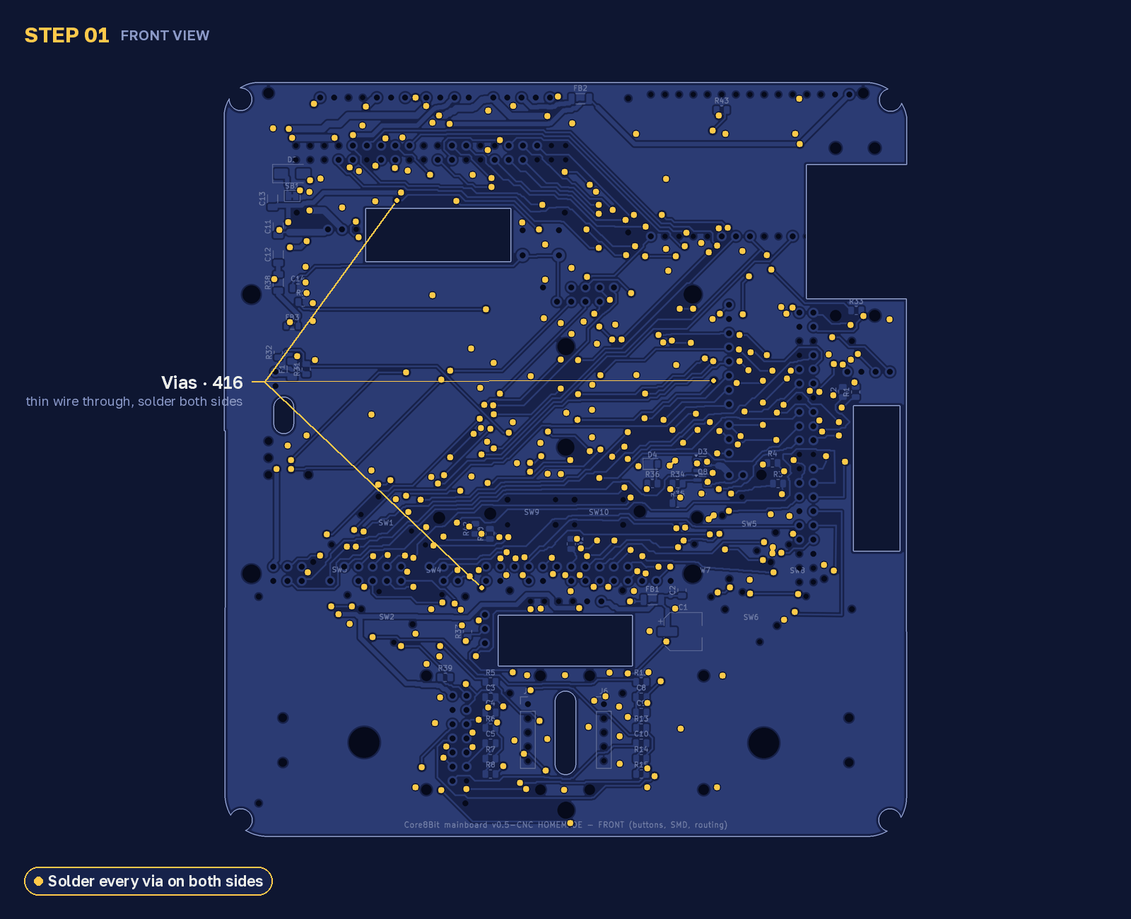
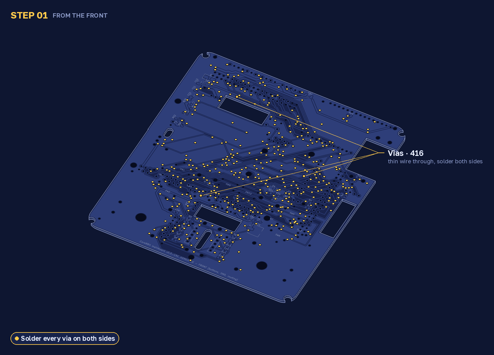
Push a thin wire through every small via hole (416 of them). Solder it on both sides and snip it flush.
02. Solder the small parts
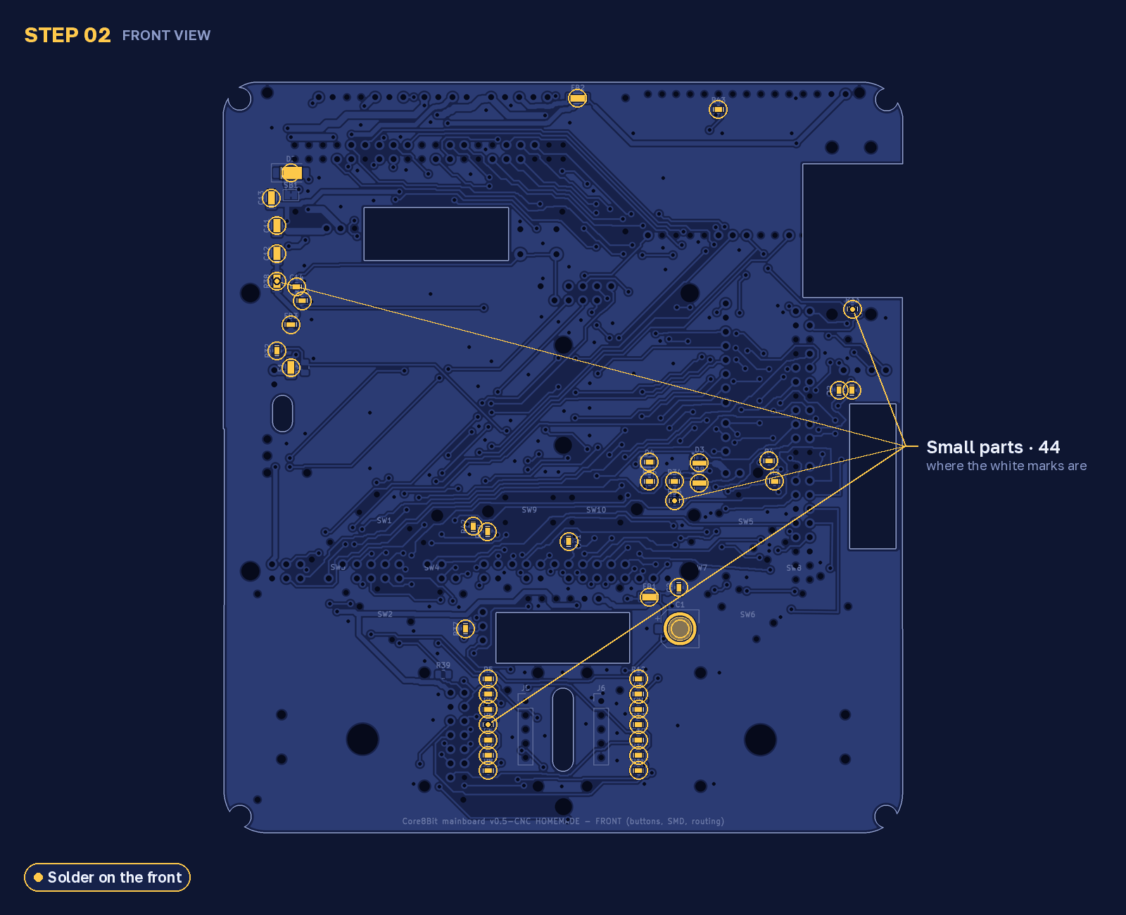
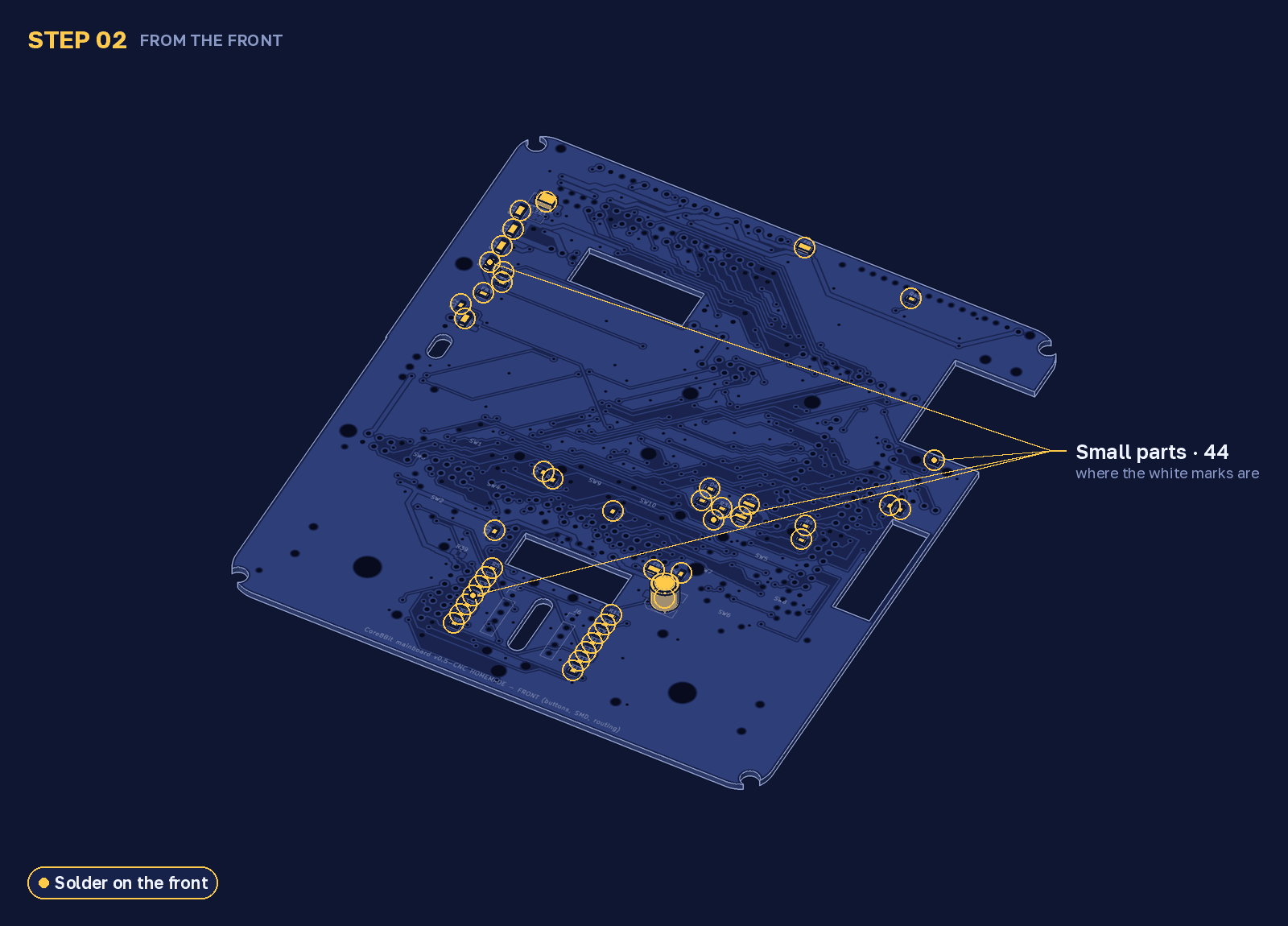
Solder the small parts on the front, where the white marks are. The list is in the quick build.
03. Add the buttons and sticks
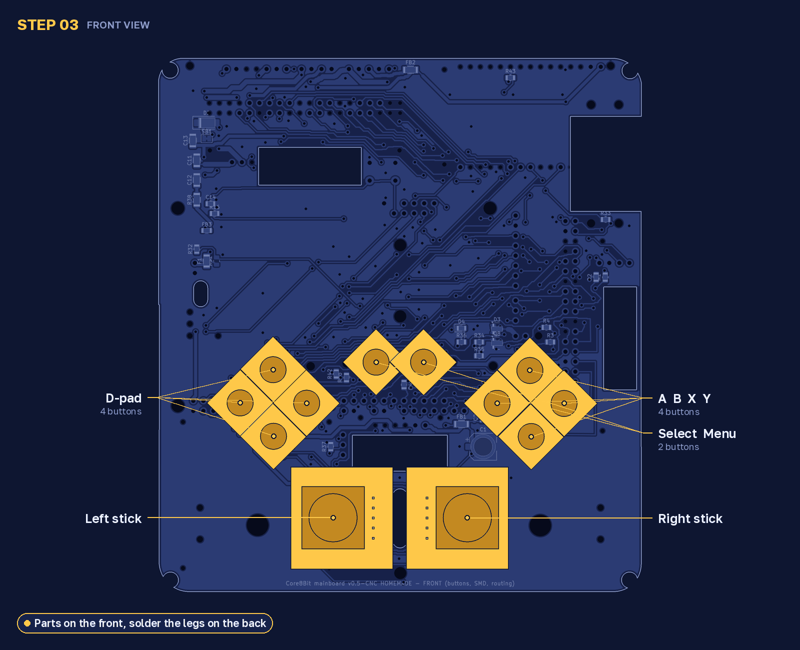
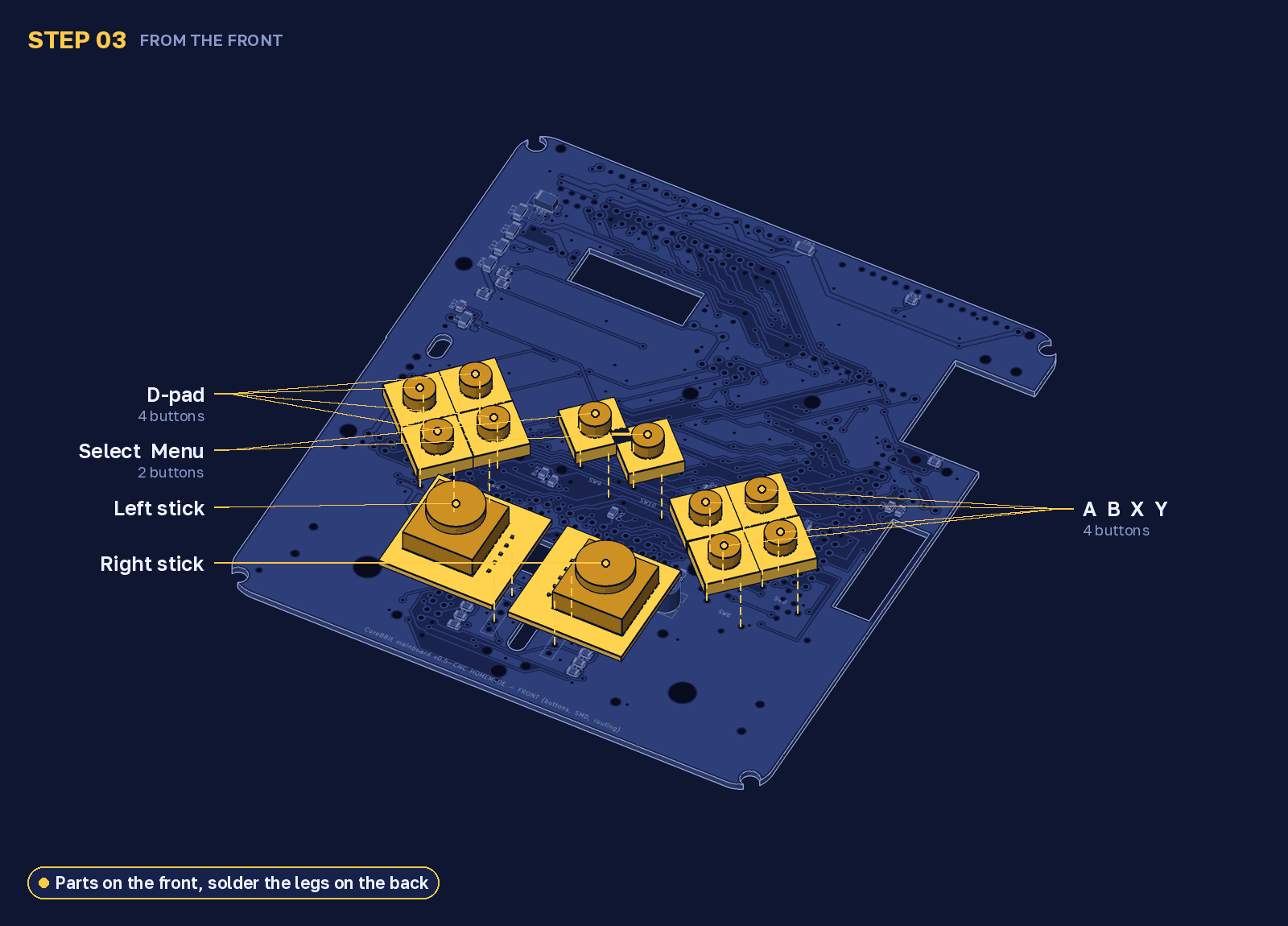
Put the 10 buttons and the two sticks on the front. Solder their legs on the back.
04. Add the power boards
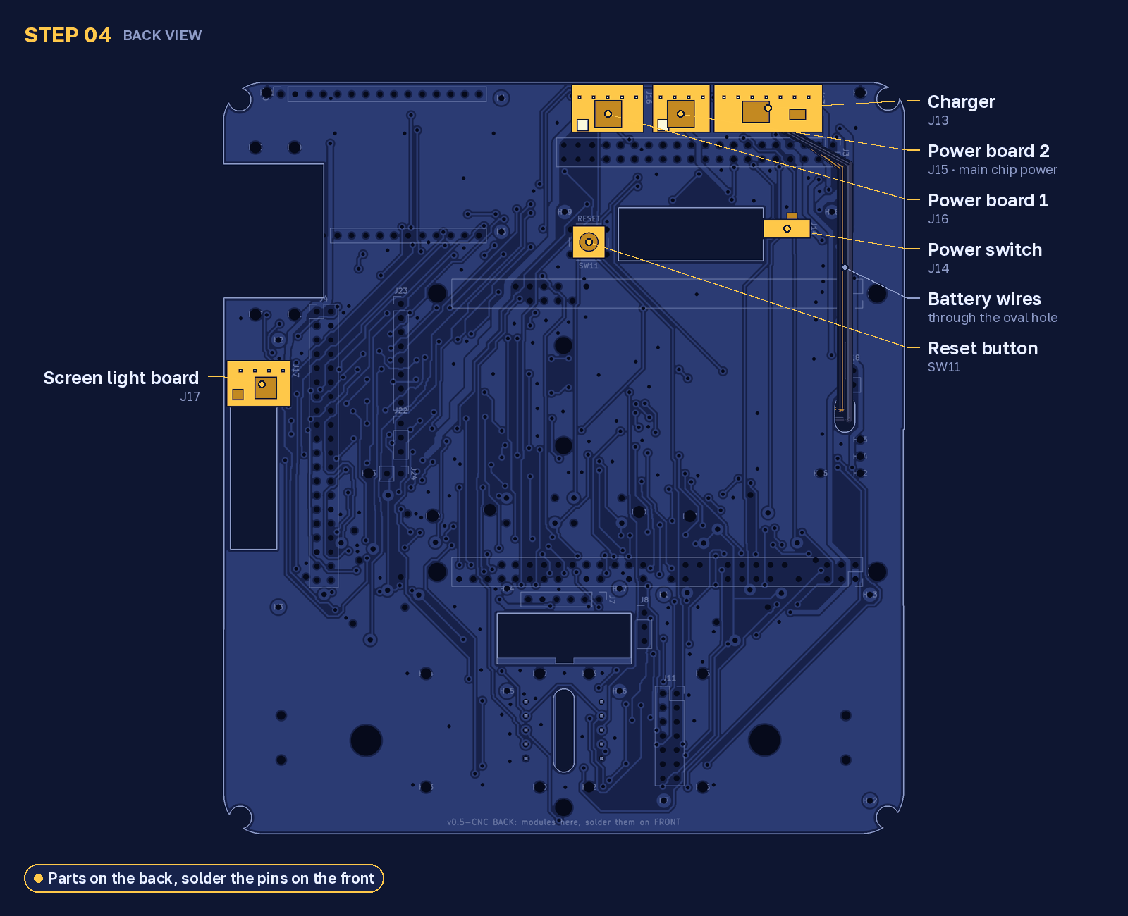
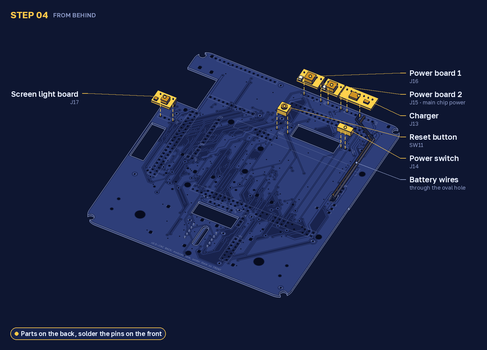
Back view: the board is turned over. Put the charger, both power boards, the switch, the screen light board and the reset button on their pins. Solder the pins on the front. Run the battery wires through the oval hole to the charger.
05. Check the 5 V
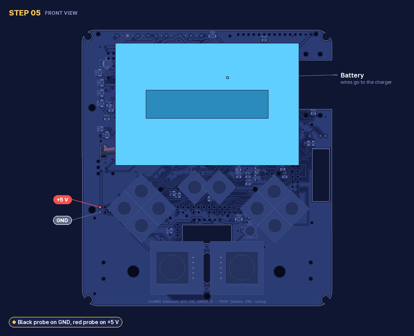
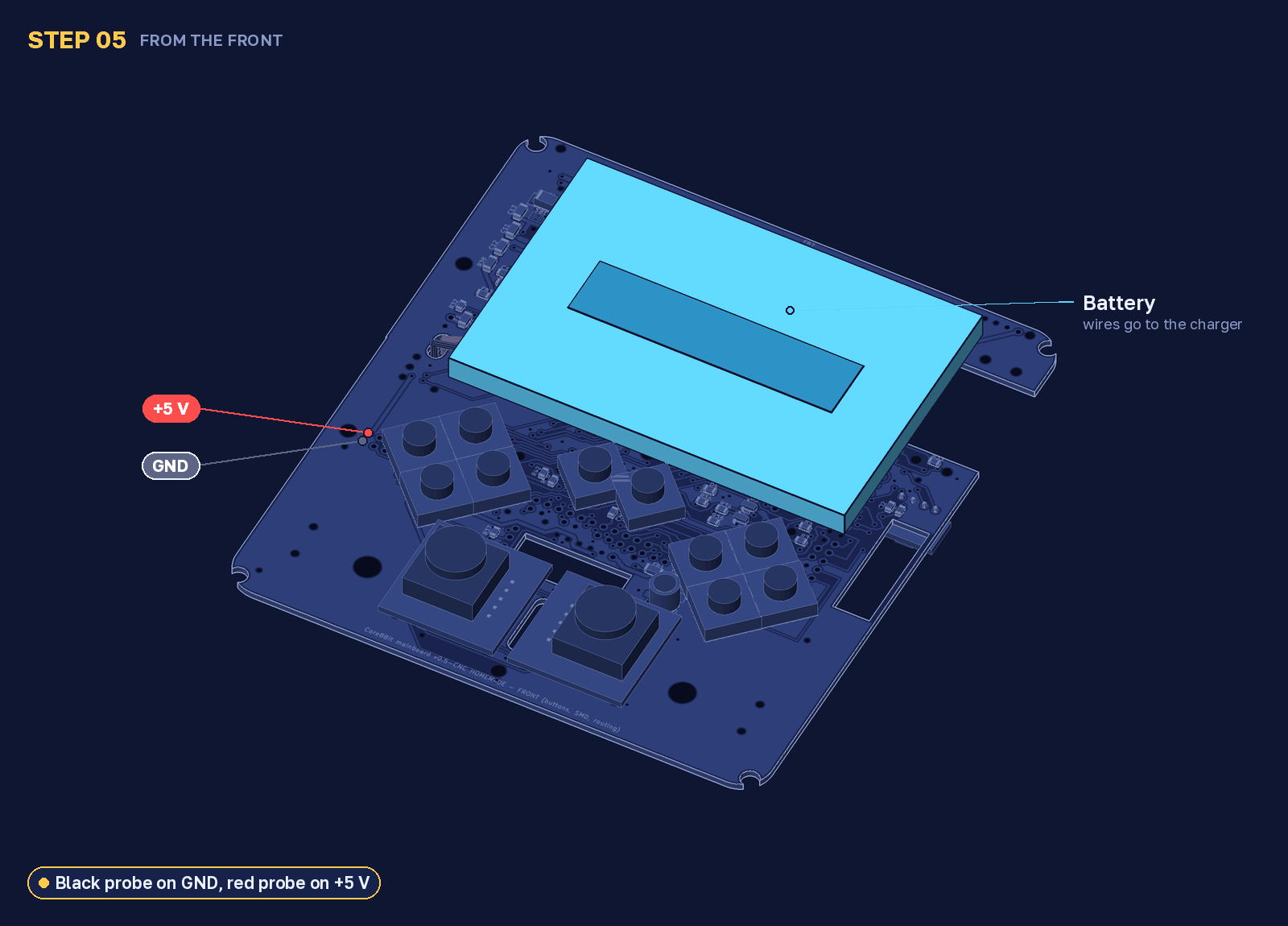
Lay the battery on the front and switch on. Black probe on GND, red probe on +5 V: it should show about 5 V. If power board 2 has a small screw, turn it until the meter shows 5.0 V. Do this before the next step.
06. Add the main chip board
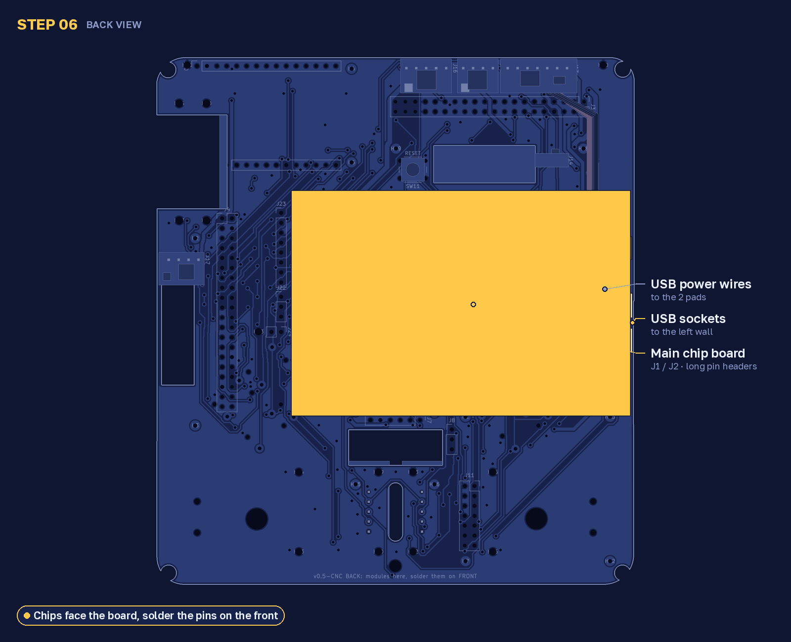
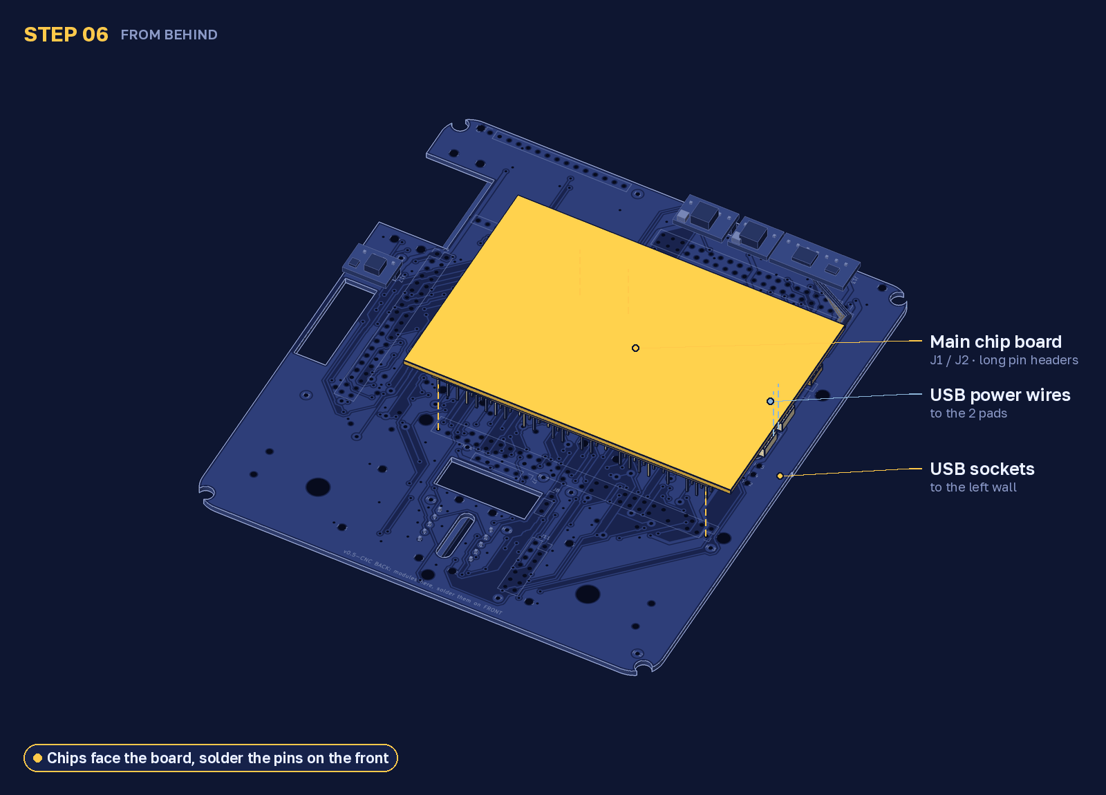
Back view. Put the main chip board on the long pins, chips facing the board, USB sockets toward the left edge. Solder on the front. Solder the two short wires from its USB socket to the two pads.
07. Add the Wi-Fi board
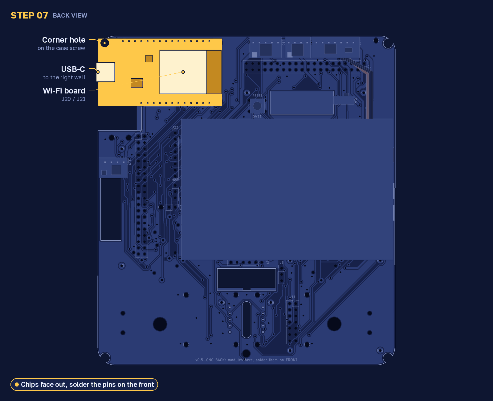
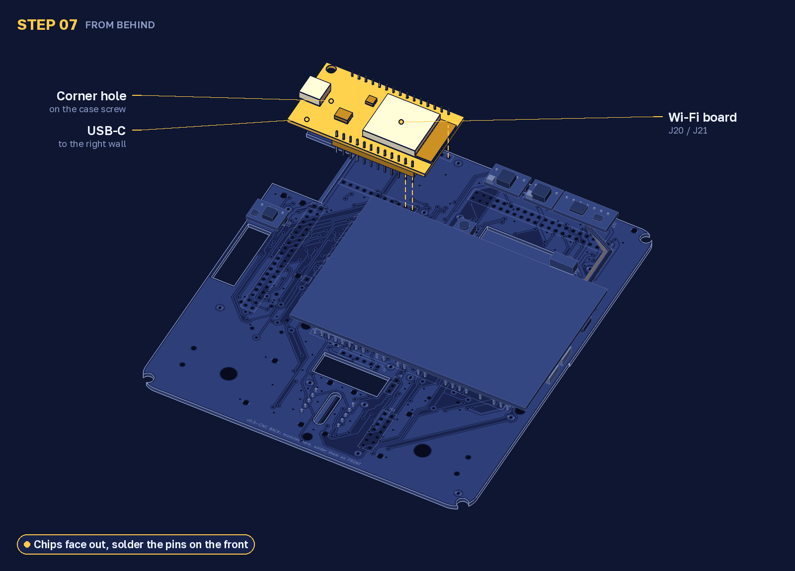
Back view. Chips face out and USB-C points to the right edge. The corner hole sits over the case screw hole. Solder on the front.
08. Add the sound boards
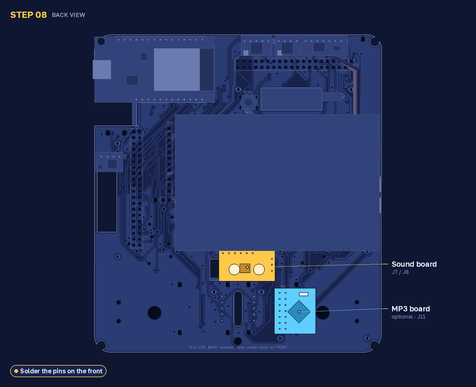
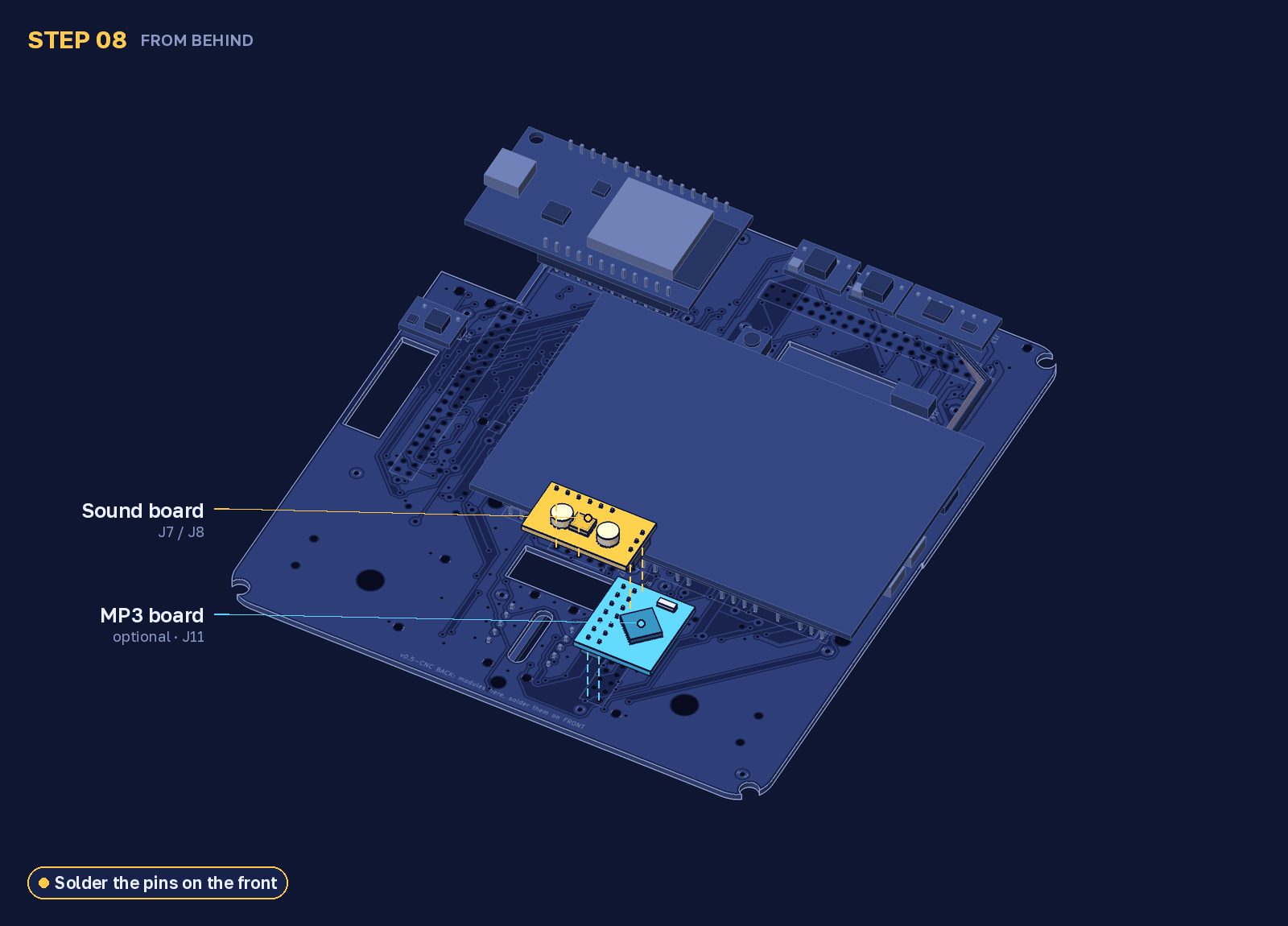
Back view. Put the sound board on its pins and solder on the front. The MP3 board is optional.
09. Add the screen adapters
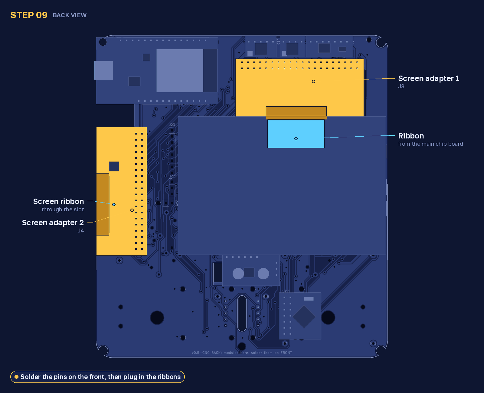
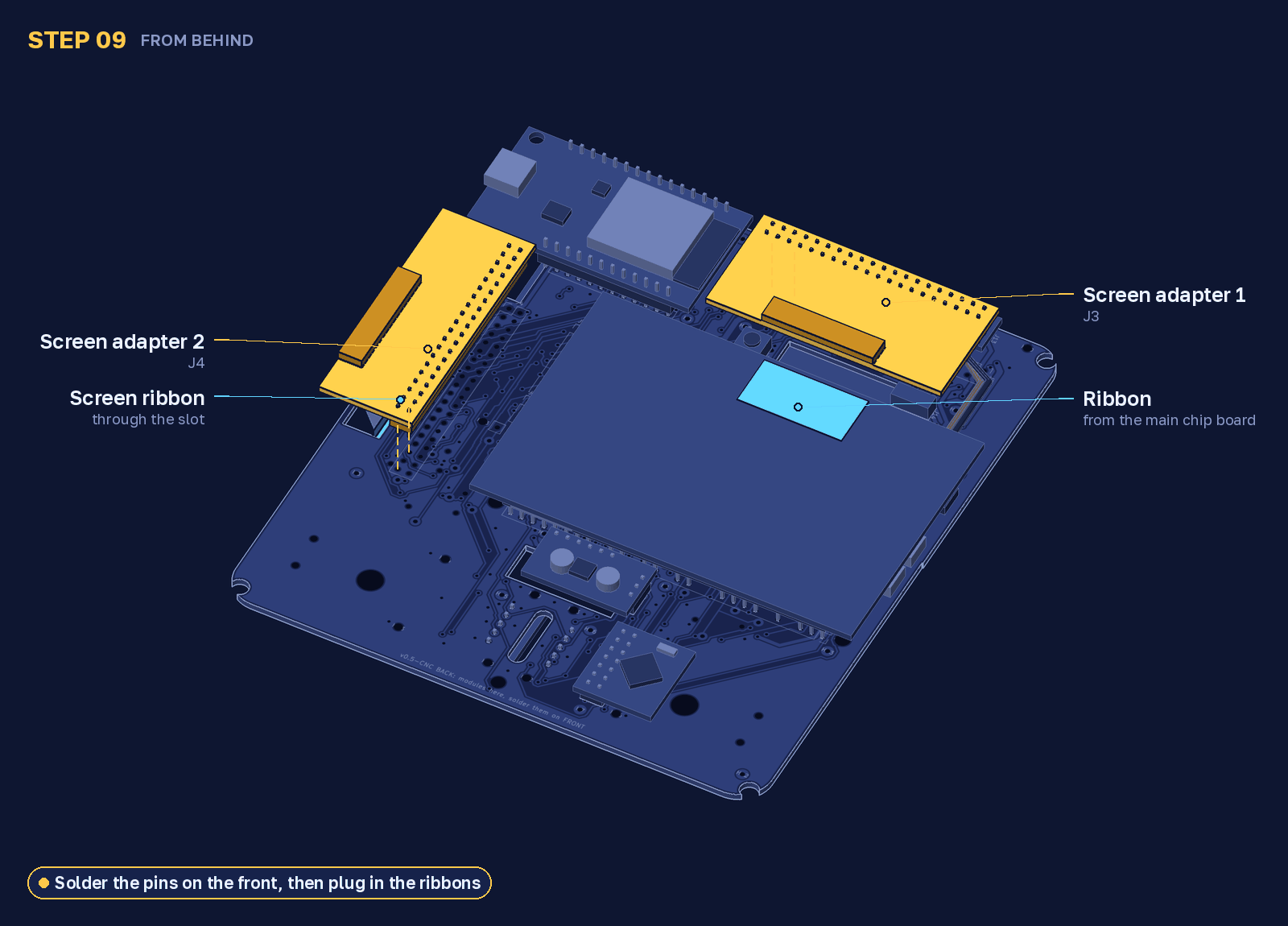
Back view. Put both screen adapters on their pins and solder on the front. Plug the ribbon from the main chip board into adapter 1. The screen ribbon goes through the slot into adapter 2.
10. Fit the screen frame
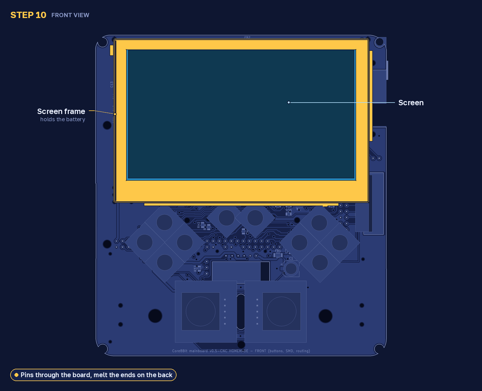
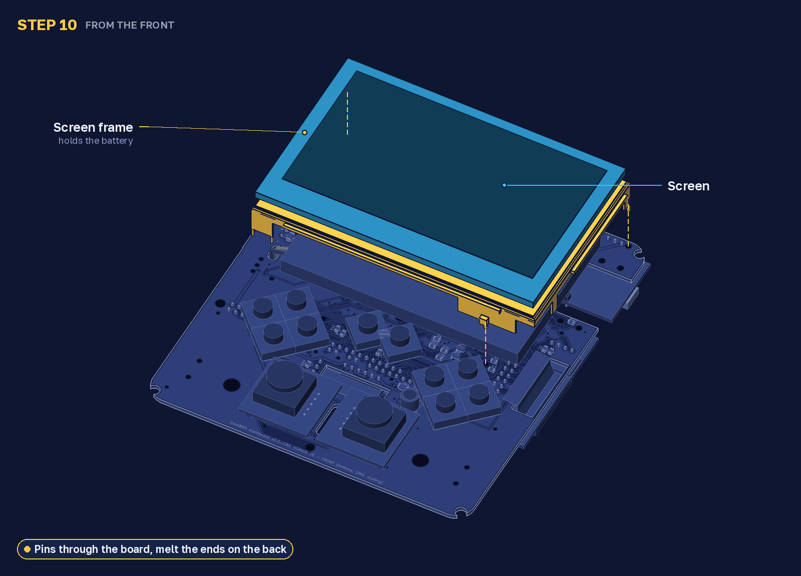
Put the screen in the frame and push the frame pins through the board, over the battery. On the back, melt the pin ends flat with the soldering iron.
11. Fit the speakers
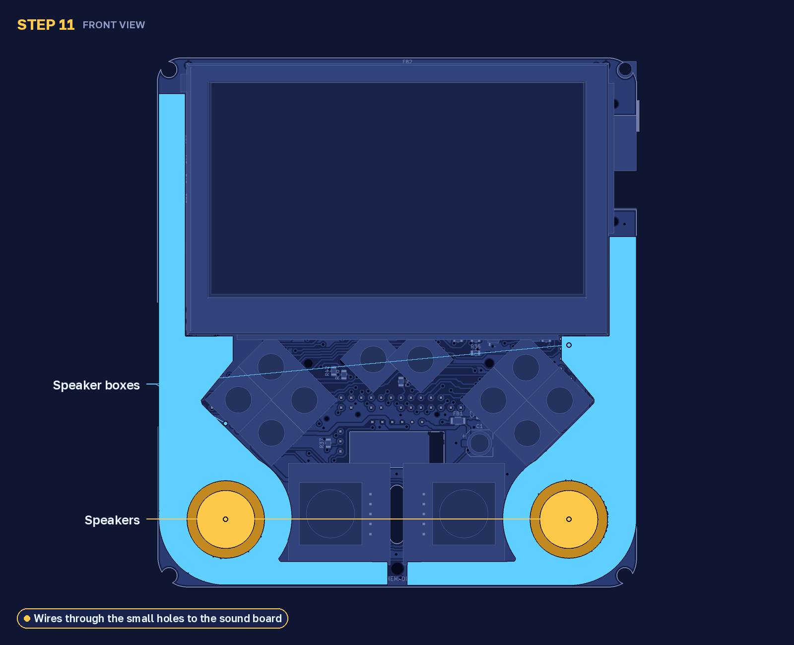
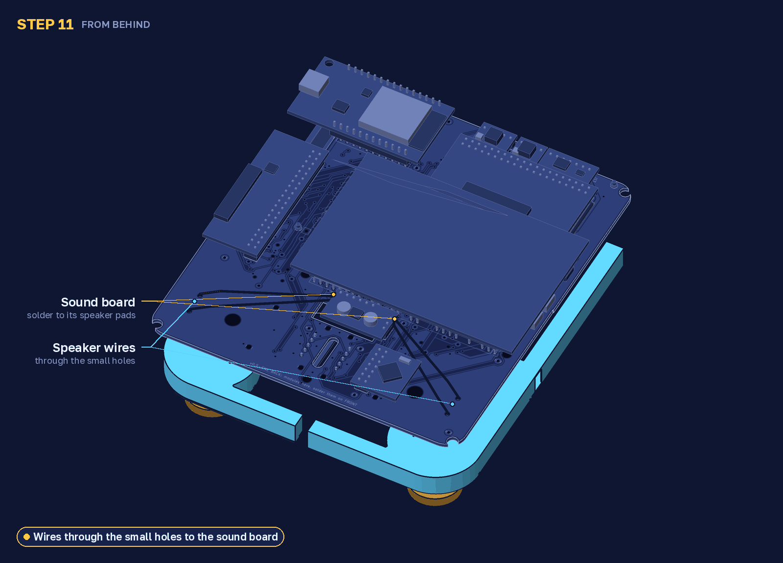
Put the speakers into their boxes. Pass each pair of wires through the two small holes next to the speaker and solder them to the sound board.
12. Check before closing
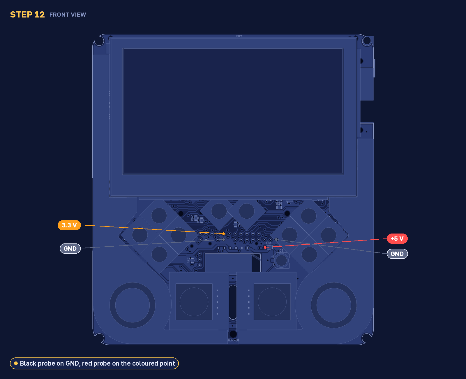
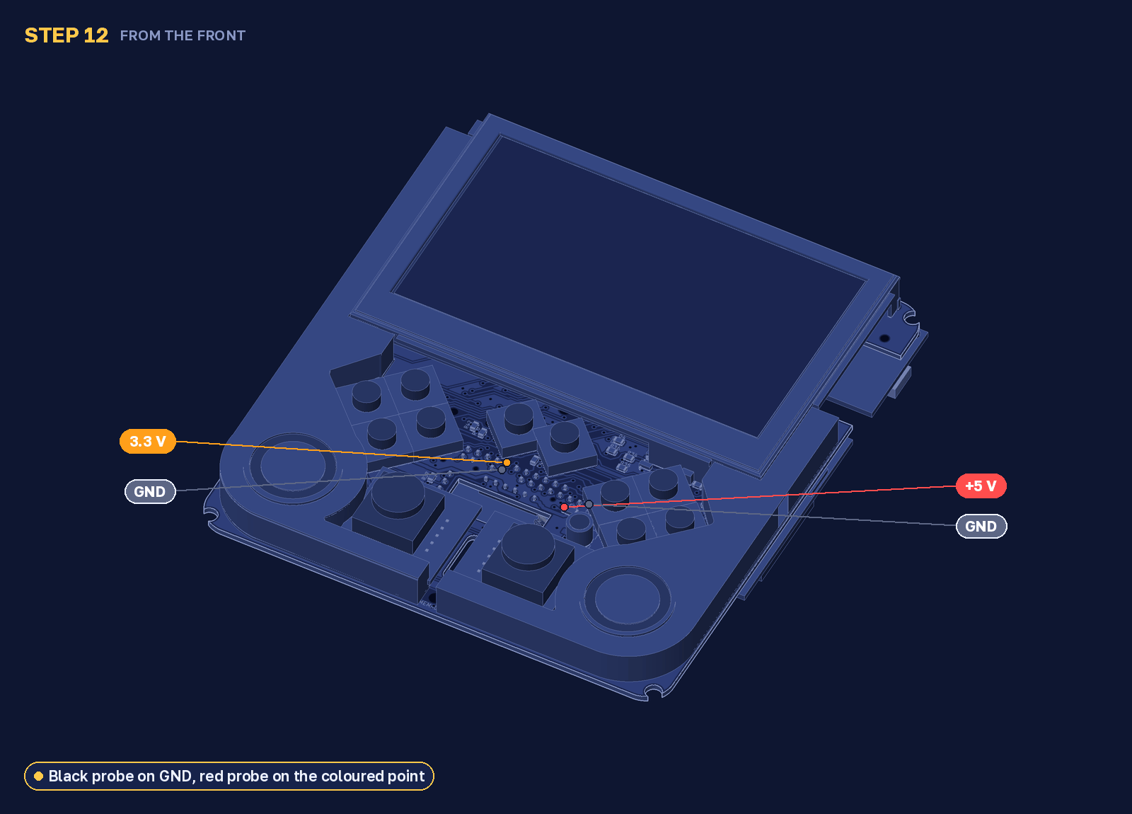
Switch on and wait for the screen to light up. Black probe on GND, red probe on the orange point: about 3.3 V. On the red point: about 5 V.
13. Close the case
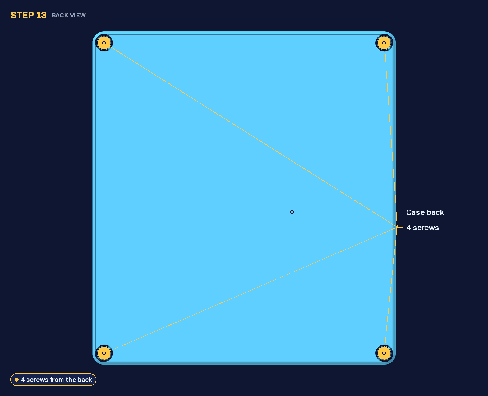
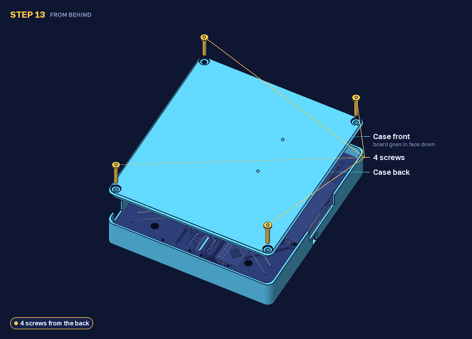
Back view. Lay the board face down in the case front. Put the case back on and tighten the 4 screws.